
Mercedes-Benz V-8 M116 3.5-ltr. M117 4.5-ltr. engines | Workshop manual cover
  • Mercedes-Benz V-8 M116 3.5-ltr. M117 4.5-ltr. engines | Workshop manual cover
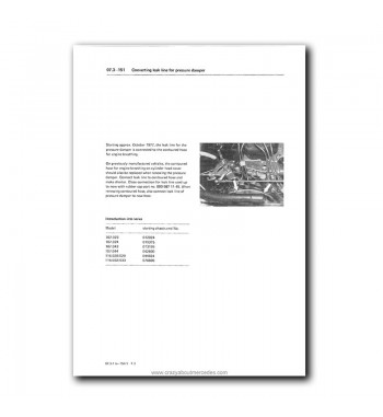
  • Mercedes-Benz V-8 M116 3.5-ltr. M117 4.5-ltr. engines | Converting leak line for pressure damper
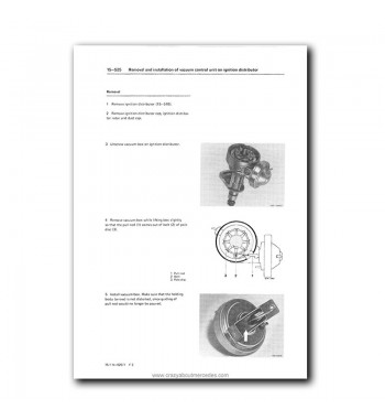
  • Mercedes-Benz V-8 M116 3.5-ltr. M117 4.5-ltr. engines | Removal and installation of vacuum control unit on ignition distributor
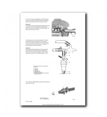
  • Mercedes-Benz V-8 M116 3.5-ltr. M117 4.5-ltr. engines | Injection valve, ring line and rubber sealing ring installation
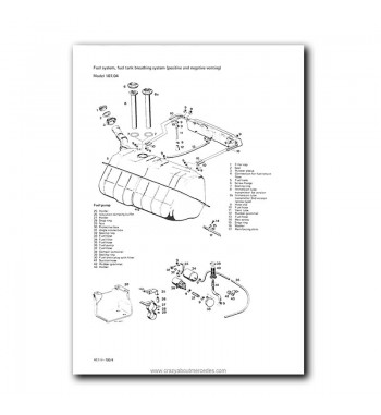
  • Mercedes-Benz V-8 M116 3.5-ltr. M117 4.5-ltr. engines | Fuel system, fuel tank breathing system

Mercedes-Benz Service Manual V-8 Engines M116 (3.5-ltr.), M117 (4.5-ltr.)

$20.00

Workshop manual for Mercedes-Benz V-8 M116 3.5-liter and M117 4.5-liter engines

Provides official service information for diagnosis, inspection, disassembly, measurement, adjustment, assembly, and repair of the early Mercedes-Benz V-8 engines in this family, with application in W108, W109, W111, W107, and W116 vehicles.

PDF in English | 572 pages | Instant download.

  • Factory manual for first-generation M116 and M117 engines
  • Includes technical data, identification, compression, leak testing, oil consumption, and engine removal
  • Contains tables, step-by-step procedures, special tools, and original technical illustrations
  • Especially useful for repair, maintenance, and restoration of classic Mercedes-Benz models
Quantity


Security payment


Digital delivery


Returns

COOKIE PREFERENCES (EU GDPR)

Cookies: We use necessary cookies for the cart and login to work. You can accept, decline, or configure non-essential cookies.

Cookie Policy  ·  Privacy Policy

Mercedes-Benz Service Manual V-8 Engines M116 (3.5-ltr.), M117 (4.5-ltr.) | PDF

Technical service coverage for Mercedes-Benz V-8 M116 3.5-liter and M117 4.5-liter engines, with applications in the brand’s classic sedans, coupés, and roadsters.

This edition covers the first generation of the Mercedes-Benz M116 and M117 V-8 engines, used in classic models from the W108, W109, W111, W107, and W116 series. Because it focuses on the early 3.5- and 4.5-liter versions, it is especially valuable for repair, maintenance, diagnosis, and restoration work on Mercedes-Benz vehicles from the late 1960s and the 1970s.

Unlike the later M116 and M117 V-8 manuals, this PDF focuses on the initial stage of the engine family, with direct coverage for engines 116.980, 116.981, 117.981, 117.982, 117.983, 117.984, 117.985, and 117.986. It includes inspection, disassembly, measurement, machining, assembly, and adjustment procedures, along with technical tables, tightening torques, special tools, and original service illustrations.

To verify the contents of this edition, you can consult the Full Index tab, where the manual groups and operations are presented.

Main topics covered in the Mercedes-Benz V-8 M116 3.5 and M117 4.5 engine manual

  • General data, engine identification, and technical specifications
  • Engine removal and installation, cylinder head, and oil pan
  • Compression, leak testing, cylinder bore evaluation, and oil consumption
  • Crankshaft assembly, connecting rods, pistons, seals, and flywheel
  • Valve train, valve adjustment, camshafts, and timing chain
  • CIS mechanical fuel injection system
  • Electronically controlled fuel injection system
  • Ignition systems and timing adjustment
  • Intake, manifolds, emission control, and engine electrical system
  • Lubrication, cooling, engine mounts, and accelerator linkage
  • Fuel system, fuel tank, and ventilation
  • Exhaust system

Mercedes-Benz models related to the M116 3.5-liter engine:

  • W107 series: 350 SL and 350 SLC
  • W108 series: 280 SE 3.5 and 280 SEL 3.5
  • W109 series: 300 SEL 3.5
  • W111 series: 280 SE 3.5 Coupe and Cabriolet
  • W116 series: 350 SE and 350 SEL

Mercedes-Benz models related to the M117 4.5-liter engine:

  • W108 series: 280 SE 4.5 and 280 SEL 4.5
  • W109 series: 300 SEL 4.5
  • W116 series: 450 SE and 450 SEL
  • W107 series: 450 SL and 450 SLC

Important clarification: the models listed above help identify the main applications related to this first generation of the Mercedes-Benz V-8 M116 3.5-liter and M117 4.5-liter engines. Some are explicitly listed in the manual, while others are included as a reference because they share the same mechanical base as the versions developed in this edition. For that reason, the content may also be useful for diagnosis, maintenance, repair, and restoration work on other technically related classic Mercedes-Benz models.

This publication corresponds to the workshop manual for the Mercedes-Benz V-8 M116 3.5-liter and M117 4.5-liter engines. For the later 3.8- and 5.0-liter variants, or the 4.2- and 5.6-liter versions, a different edition applies. Before buying, the best approach is to verify the exact engine code installed in the vehicle and review the Complete Index tab. The file is supplied in PDF format with bookmarks for easier chapter navigation, preserves the original technical content of the printed edition, and can be consulted from a PC, tablet, or smartphone, while also allowing you to print only the pages needed for each job.

Item details:

  • Format: PDF
  • Language: English
  • Pages: 572
  • File size: 67.5 MB
  • Delivery method: Download link

Frequently asked questions about the Mercedes-Benz M116 3.5 and M117 4.5 engine manual

How can I tell whether this M116 and M117 manual is the right one before buying?

The safest way is to check the exact engine code installed in the vehicle. This edition corresponds to the first generation of the M116 and M117 V-8 family and covers the 3.5- and 4.5-liter variants, not the later 3.8- and 5.0-liter versions or the 4.2- and 5.6-liter versions.

Is this PDF only for 450 models, or can it also help with other early V-8 applications?

It is not limited to the 450 models. It can also be useful for vehicles fitted with the M116 3.5 and M117 4.5 engines used in classic Mercedes-Benz series such as W108, W109, W111, W107, and W116.

Does the content include internal engine work, or only basic maintenance tasks?

It includes much more than basic maintenance. The manual covers compression testing, leak testing, cylinder evaluation, oil consumption, engine removal, cylinder head work, crankshaft assembly, pistons, seals, flywheel service, and other deeper repair procedures.

Does it include information on valve timing, valves, and the timing chain?

Yes. The manual includes valve adjustment, hydraulic compensating elements, camshaft timing, chain tensioner work, timing chain replacement, guide rails, and other procedures related to the V-8 valve train and timing system.

Does it cover injection and ignition systems?

Yes. Among the groups covered are the CIS mechanical fuel injection system, the electronically controlled fuel injection system, and various ignition and timing procedures, which are especially useful for diagnosing classic Mercedes-Benz engines.

Is it a good reference for restoring classic Mercedes-Benz models with these V-8 engines?

Yes. Because of its focus on the early M116 and M117 variants, its technical tables, workshop procedures, and original illustrations, it is a very useful reference for serious restoration, correct maintenance, and repair of classic Mercedes-Benz models equipped with these V-8 engines.

Mercedes-Benz V-8 Engine Manual for 3.5-liter M116 and 4.5-liter M117 Engines | Index

This index lists the main sections and part numbers included in the Mercedes-Benz Service Manual for V-8 Engines M116 (3.5-liter) and M117 (4.5-liter).

The headings in the manual's index follow the technical designation and numbering of each part.
00 General, Technical Data

  • 00-005 Instructions for use of service manual
  • 00-010 Engine and vehicle identification
  • 00-015 Vehicle identification number locations
  • 00-020 Technical data

01 Engine removal and installation, cylinder crankcase, cylinder head, engine breathing

  • 01-010 Checking compression pressure
  • 01-015 Checking cylinders for leaks
  • 01-020 Evaluation of cylinders bores
  • 01-025 Measuring oil consumption
  • 01-030 Removal and installation of engine (oil capacity)
  • 01-040 Engine breather - Functional description
  • 01-110 Measuring, boring and honing cylinder bores
  • 01-120 Facing cylinder crankcase parting surface
  • 01-210 Removal and installation of timing housing cover
  • 01-220 Installation and centering of intermediate flange
  • 01-222 Removal and installation of end cover
  • 01-310 Removal and installation of complete oil pan
  • 01-415 Removal and installation of cylinder head
  • 01-418 Facing cylinder head parting surface
  • 01-420 Pressure-testing cylinder head

03 Crankshaft assembly

  • 03-310 Checking, renewing and tightening connecting rod bolts
  • 03-313 Reconditioning and squaring connecting rod
  • 03-316 Removal and installation of pistons
  • 03-318 Checking and reconditioning of crankshaft
  • 03-320 Mounting of crankshaft
  • 03-324 Renewing front crankshaft radial sealing ring
  • 03-327 Renewing rear crankshaft radial sealing ring
  • 03-330 Removal and installation of radial ball bearing and closing ring in crankshaft
  • 03-342 Removal and installation of hub, vibration damper and pulley
  • 03-345 Checking and correcting adjustment of TDC transmitter
  • 03-350 Removal and installation of crankshaft sprocket
  • 03-410 Removing and installing flywheel and driven plate
  • 03-420 Refinishing flywheel
  • 03-430 Renewing ring gear

05 Engine timing, valves

  • 05-210 Inspection and adjustment of valve clearance
  • 05-211 Inspection and renewal of hydraulic valve clearance compensating elements
  • 05-212 Renewal of threaded bushing with valve adjusting screw
  • 05-213 Inspection and correction of basic position of hydraulic valve clearance compensating elements
  • 05-215 Checking and adjusting of camshaft timing
  • 05-220 Removal and installation of camshaft
  • 05-225 Grinding camshaft bearing journals
  • 05-230 Removal and installation of rocker arms
  • 05-250 Removal and installation of valve springs
  • 05-260 Checking valve springs
  • 05-270 Replacement of valve stem seals
  • 05-280 Checking and machining valves
  • 05-285 Inspection and renewal of valve guides
  • 05-290 Renewal of valve seat rings
  • 05-291 Machining valve seat
  • 05-310 Removal and installation, inspection of chain tensioner
  • 05-320 Renewing timing chain
  • 05-330 Removal and installation of tensioning rail
  • 05-340 Removal and installation of slide rails
  • 05-434 Removal and installation of intermediate sprocket ignition distributor drive
  • 05-440 Removal and installation of guide sprocket

07.3 Mechanically controlled gasoline injection system (CIS)

  • 07.3-100 Adjustment of idle speed
  • 07.3-105 Checking, adjusting of-off ratio
  • 07.3-110 Checking, regulating engine
  • 07.3-120 Checking fuel pressures and for internal leaks
  • 07.3-125 Checking choke system
  • 07.3-130 Checking delivery of fuel pump
  • 07.3-135 Checking injection valves
  • 07.3-146 Checking speed stabilization at idle, engine 116.98 (3.5)
  • 07.3-151 Converting leak line for pressure damper
  • 07.3-152 Adjusting throttle valve switch (USA) 1980
  • 07.3-160 Checking for constant delivery of fuel distributor
  • 07.3-165 Checking fuel pump relay
  • 07.3-199 Mixture preparation
  • 07.3-200 Removal and installation of mixture controller
  • 07.3-205 Renewing fuel distributor
  • 07.3-210 Reconditioning system pressure regulator and pressure compensating valve
  • 07.3-215 Removal and installation of injection valves
  • 07.3-220 Renewing air flow sensor
  • 07.3-225 Removal and installation of mixture controller with air guide housing
  • 07.3-230 Removal and installation of throttle valve housing
  • 07.3-240 Renewing warm-up compensator
  • 07.3-242 Subsequent installation of safety switch on air flow sensor
  • 07.3-245 Renewing air flow sensor plate, centering, checking zero position of air flow sensor plate and adjusting
  • 07.3-270 Removal and installation of fuel storage reservoir
  • 07.3-275 Removal and installation of fuel filter
  • 07.3-280 Removal and installation of fuel pump
  • 07.3-281 Renewing holder for fuel pump, fuel filter and fuel reservoir
  • 07.3-282 Converting fuel pump assembly
  • 07.3-283 Subsequent installation of separate check valve on fuel pump
  • 07.3-285 Survey fuel pump
  • 07.3-500 Functional description CIS A (USA) model year 1980 (engine 117)

07.4 Electronically controlled gasoline injection system with regulation

  • 07.4-035 Initial jobs for testing electronically controlled gasoline injection system
  • 07.4-040 Testing electronically controlled gasoline injection
  • 07.4-100 Adjustment of idle speed
  • 07.4-110 Regulating engine
  • 07.4-120 Checking fuel pressure and for leaks in ring line
  • 07.4-125 Checking starting device
  • 07.4-130 Checking delivery pressure and delivery capacity of fuel pump
  • 07.4-135 Checking injection valves
  • 07.4-140 Adjustment of throttle valve switch
  • 07.4-215 Removal and installation of injection valves
  • 07.4-220 Renewing fuel hoses on injection valves
  • 07.4-221 Replacing fuel hoses on ring line
  • 07.4-223 Renewing protective sleeves on injection valves
  • 07.4-225 Injection valves with double sealing edge connection
  • 07.4-230 Removal and installation of throttle valve housing
  • 07.4-235 Illustrated table mixture preparation
  • 07.4-270 Removal and installation of fuel filter and fuel pump
  • 07.4-275 Subsequent installation of modified fuel hose to prevent compressional vibrations at fuel pump (model 107.023/043)
  • 07.4-300 Adjusting regulating linkage
  • 07.4-310 Removal and installation of engine longitudinal regulating shaft
  • 07.4-320 Removal, installation and adjustment of front wall regulating shaft
  • 07.4-330 Removal and installation of accelerator pedal

07.5 Ignition system

  • 07.5-500 Checking and adjusting closing angle (dwell angle) and firing point
  • 07.5-503 Removing and preventing on breaker points
  • 07.5-505 Renewing breaker points
  • 07.5-510 Removal and installation of ignition distributor
  • 07.5-519 General description of breaker-controlled transistorized ignition
  • 07.5-520 Testing contact (breaker) controlled transistorized ignition

09 Intake system. Air cleaner

  • 09-400 Removal and installation of intake pipe, renewing gasket
  • 09-400a Removal and installation of air cleaner
  • 09-410 Renewing intake pipe (intake pipe removed)
  • 09-420 Removal and installation of air filter

13 Belt drives

  • 13-335 Notes concerning renewing and tensioning of V-belts
  • 13-340 Replacing and tensioning V-belts

14 Intake manifold, exhaust manifold. Emission control system

  • 14-001 Functional characteristics
  • 14-050 Operation
  • 14-100 Test program
  • 14-150 Wiring diagrams
  • 14-450 Removal and installation of intake manifold upper and lower half, renewing gaskets
  • 14-455 Renewing intake manifold (intake manifold removed)
  • 14-470 Removal and installation of exhaust manifold
  • 14-472 Survey exhaust manifold

15 Electrical system, engine

  • 15-501 Testing and adjusting ignition timing (breakerless transistorized ignition system)
  • 15-510 Removal and installation of ignition distributor
  • 15-525 Removal and installation of vacuum control unit on ignition distributor
  • 15-528 Notes concerning jobs on breakerless transistorized ignition system
  • 15-530 General description of breakerless transistorized ignition system TSZ 4
  • 15-562 Testing breakerless transistorized ignition system TSZ 4
  • 15-571 Operation of vacuum retard adjustment

18 Engine lubrication, engine oil cooling

  • 18-005 Oil circuit, oil pressure, pressure relief and bypass valve, oil filter
  • 18-210 Removal and installation of oil pump

20 Engine cooling, coolant hoses, radiator

  • 20-005 Coolant circuit and engine cooling
  • 20-010 Draining and filling-in of coolant - anti-freeze table
  • 20-015 Cleaning the cooling system
  • 20-110 Removal and installation of coolant thermostat
  • 20-210 Removal and installation of coolant pump
  • 20-225 Sealing coolant pump
  • 20-310 Viscofan coupling, temperature-controlled
  • 20-320 Viscofan coupling, speed-controlled
  • 20-420 Removal and installation of radiator
  • 20-430 Checking radiator or expansion tank cap

22 Engine mounts

  • 22-210 Removal and installation of engine mounts
  • 22-240 Removal and installation of engine shock absorber

30 Accelerator control, regulation

  • 30-300 Adjusting regulating linkage
  • 30-320 Removal, installation and adjustment of front wall regulating shaft
  • 30-330 Removal and installation of accelerator pedal
  • 30-335 Lubricating regulating linkage and regulating shaft

47 Fuel system

  • 47-700 Removal and installation of fuel tank
  • 47-700a Removal and installation of fuel tank
  • 47-705 Removal and installation of fuel expansion tank (model 107.04)
  • 47-705a Removal and installation of fuel expansion tank
  • 47-706 Installation of modified fuel tank and fuel expansion tank (model 107.043)
  • 47-710 Removal and installation of immersion tube transmitter
  • 47-710a Removal and installation of immersion tube transmitter
  • 47-715 Functional description of immersion tube transmitter for fuel gauge
  • 47-715a Operation of immersion tube transmitter for fuel gauge
  • 47-720 Functional description of fuel tank breathing system (positive and negative venting)
  • 47-720a Operation of fuel tank positive and negative venting system
  • 47-800 Fuel evaporation control system
  • 47-800a Fuel evaporation control system (AUS) (J) (USA)
  • 47-850 Fuel cooler (J) (USA)

49 Exhaust system

  • 49-100 Removal and installation of exhaust system
  • 49-100a Removal and installation of exhaust system
  • 49-101 Exhaust system - technical modification
  • 49-450 Removal and installation of exhaust manifold